Also known as Spot-to-Line, or Fiberoptic Line, or Fiberoptic Light line, FTI manufactures standard fiberoptic light lines from .125″ to over 4 feet in length.
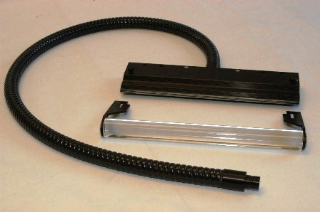
In the fiberoptic line photo below, you might also notice the optional cylindrical lens and holder, which serves to focus diverging line output, concentrating output into a thin, bright, fairly uniform line of light. Because the lens concentrates the power, the overall power density will increase by a factor of 10.
Fiberoptic lines have two main applications.
- For sensing, a typical light line will transmit signal from the line side to the spot side, where a photodetector collects and processes the signal. Light lines are also used frequently to “pick-up” scattered or reflecting light from a laser and rotating mirror combinations.
2. For “shaped” illumination, almost all fiberoptic input starts out as a circular spot of light. In the case of a fiber line, an inexpensive projector bulb in a fiberoptic light source can illuminate the entire width of a document or web of paper.
FTI concentrates its effort designing and manufacturing application-specific custom fiberoptic lines. However, FTI also manufactures standard light lines in a wide variety of sizes and shapes, with the following features:
- Light line lengths of .125″ (3mm) or less up to lines 4 feet (122cm) long.
- Excellent fiber packing and alignment using proprietary manufacturing techniques, compares favorably with “wound” lines in quality without associated cost.
- The standard bundle length of 40″ (1M) is suitable for most applications.
- Fixture holes in the all black anodized aluminum body assists in mounting.
- Black anodized aluminum adapter is attached to the PVC covered metal sheathing for durability and long-term performance.
- Ends of the fiber line are flush with the end of the housing to insure full width coverage of the output or collection of the signal…whichever is required..
Light Line Design Considerations
To optimize the performance of a light line as emitter or receiver, it’s important to match the fiberoptic active area of the line to the active area of the lamp’s focal spot or the detector being used. The usual method of design begins by describing the desired line length. Then, the optimal spot size of the lamp or area of the photo detector is identified, and finally, a line width is calculated to work best with the application.
To ensure consistent performance, the fiber nearer the spot (proximal) end should be randomized to minimize inconsistencies of the lamp or detector, and the fiber at the line (distal) end should be parallel, tightly nested, and uniformly placed to focus the output beam, minimize output skewed output, and maintain uniformity.
FTI uses a unique, proprietary method of creating light lines, resulting in a repeatable, high quality, cost effective product.
Occasionally an application will require more power from the line end than the device at the spot end can output. In this case, FTI will manufacture the line using two (or more) inputs with the fiber from both inputs uniformly dispersed throughout the line, maintaining consistent energy distribution. Each input disperses light energy along the entire length of the line.
Sizing Guidelines for our Light Lines
Try to select a line length longer than the width you are inspecting; all fiberoptic lines experience light fall-off at near each end.
For web scanning applications, assuming a typical projector lamp focal spot diameter of .55″, 1 input for every 16″ (.4M) of line will create a line width of about .015″ (.38mm) – an area most traditional lamps can fill with a focused spot.
If you’re using a strobe, inputs with an active diameter of up to .8″ (20mm) could be used, so the line length per input can be doubled, (or the power per inch can be increased to improve processing speed and accuracy).
Of course, your particular application is the overriding determining factor, and your goal should be to optimize line performance, using as little fiber (and the fewest number of inputs) as possible to minimize cost.
To ensure effective application, we work with you to determine exactly what design will best suit your needs. Then, we’ll help determine how uniform the response must be across the face of the line for your use. Finally, each spot-to-line is scanned on our automatic transmission fixture to ensure compliance with the developed specification, or it’s checked in a custom test fixure you provide. A hard copy record of the results can be provided with each part shipped. You’ll know the quality of the part when you receive it.
Options
FTI manufactures light lines in multiple configurations and shapes. Dual, triple and quad (or more) heads, unique housing/fixturing shapes and sizes, bundles of varying lengths, fiber of various types, and line widths of varying sizes can be produced to your specifications or one we develop for you. Finally, high heat, vacuum or pressure applications require special consideration.