The term “Randomization” is really a misnomer in the world of fiber optics.
As it relates to fiber optics, “randomization” is actually a purposeful placement of fibers within a ferrule. The process itself can be automated or done by hand. Varying degrees (and types) of randomization result from various methods used. Most randomization processes are performed by hand, so experience counts!
Fiber is randomized for two basic reasons. The most common reason is to help “mix” the “hot” and “cold” spots of light energy (from a source) to make the output (or signal) more uniform. (Assuming fiber is distributed uniformly at the output.)
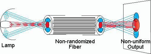
In the illustration above, energy areas of greater and less intensity are transmitted through the fiber bundle. Because the fiber bundle is assembled with most individual fibers undisturbed, the resulting output basically mirrors the input, which is non-uniform.
If the subject being illuminated is in close proximity to the fiber output, the non-uniform effect is greater than if the subject is further away, because the light has less chance to mix. The non-uniform effect is greatest if a focusing lens is used.
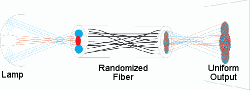
When the fiber is purposefully mixed (or in fiber optics terms, randomized), the relative input position of each fiber changes from its position at the output. Therefore, the light each fiber accepts at the input exits at a different location within the output. The resulting change in position helps mix areas of less and greater intensity, producing a uniform spot of light, even if a lens is used to focus the output.
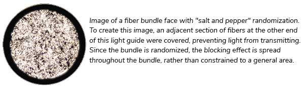
The degree of uniformity is affected by the quality or type of randomization. Very good randomization looks like “Salt and Pepper” when viewing the input. (See the photo below.)
The second purpose of randomization relates to construction of multibranch components. For these configurations (bifurcated, trifurcated, quadfurcated, etc.) randomization techniques are used at the common end to ensure energy is evenly distributed over all branches.
Generally speaking, randomization is recommended when sending energy to a sensor (CCD, Photonic, or other) to maximize signal consistency. For machine vision, randomization takes on added importance, as most recognition software evaluates changes in contrast or color to perform properly. Uniform light reduces the chance of generating misleading results.
When Randomization Is Not Required
Randomization is not necessary for most applications involving human interaction. The brain cannot discern different intensity values when so much energy is present. (Everything looks very bright.)
As the distance from the output increases, light from a fiber bundle has better mixing ability. More intense areas mix with less intense areas over the area of influence. Therefore, randomization may not be required if the component is lighting an area far from the output end.
In light line (spot-to-line) construction, if the line is comprised of more than one row of fiber, and made by layering fiber ribbons, randomization is built in, so the added step (and cost) of randomizing the bundle is not necessary.
In 2D ring light applications (or shallow depth-of field-conditions), the output is focused to a spot at an optimal working distance, “mixing” the output at the focal point. Typically, randomization is not required.
What Randomization Will Not Do
While randomization does improve non uniform lamp output, Randomization cannot compensate for differences in intensity from lamp to lamp. Randomization can only help make the output uniform.
Furthermore, if the source is extremely non uniform, randomizing the fiber will improve the output, but may not eliminate non-uniformity.
If the lamp or source creates a very concentrated spot of energy with rapid intensity fall off from the center, and that energy is projected on to a relatively small area of fibers, a small number of fibers will transmit the bulk of the energy (and whatever non-uniformity exists within the focal spot). (To minimize this condition… size the bundle to match the focal spot.)
Randomization will produce uniformity over the fiber bundle’s face, but not over a projected area. Because light from each fiber exits as a cone, not a straight beam, the light from one fiber mixes with light from the adjacent fiber. The result will always produce a bright center and less bright output at the edge of the beam. However, the beam profile will be very uniform (very normal distribution curve).
If you need a projected beam uniform edge to edge, use a laser. Some special holographic diffusers might also help produce this effect using typical vision light sources and fiber bundles.
Design Considerations
Randomization requires two criteria: a minimum length of fiber to perform the process and added space inside the sheathing to contain the resulting increase in diameter.
Sheathing ID May Increase
In the randomizing illustration above, you might notice randomizing fiber looks like braiding hair. As a matter of fact, the actual process looks very similar, with similar results. Cross-sectional diameter of the bundle increases because the fibers are crisscrossed rather than lying parallel. Therefore, a fiber bundle fitting nicely into a .125″ (3mm) ID sheath may require a .145 ID sheath to be randomized. We recommend increasing the sheathing ID by 30%.
Additionally, an increase in cross section diameter increases the bend radius. Even if the fiber has plenty of room inside the sheathing, randomizing will make the bundle stiff (and more bend resistant) along the section where randomization is done. Most manufacturers try to randomize within the mechanical housing (if there is one), avoiding the need to change sheathing ID while keeping the bundle flexible.
Minimum Length is Required
Because the randomization process crisscrosses fibers, the technician must exert care to realign the fibers in the input (or output) ferrule. If the fibers are bonded and polished while still crisscrossed, a skew condition will result. To be safe, try to specify the common end with at least 8″ (400mm) length from input ferrule to the opposite end or junction point (for furcated assemblies).