What follows is a general description of fiber assembly in most commonly used forms. For more fiber application insight, see our blog about “Glass vs Plastic”
Most fiber manufacturers would agree, single fiber assembly is referred to as “jumper cable assembly”, or “patch cord assembly”. When two or more individual fibers are gathered inside a termination, it is commonly referred to as “bundle assembly”.
A “bundle assembly”, is (usually) made of a number of the same sized individual fibers. They have been cut to the same overall length, inserted into sheathing, and terminated with ferrules or connectors. They may be single channel, bifurcated (two) channels, or multi-channeled.
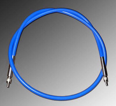
The vast majority of patch cord configurations use connectorized terminations designed to align the fiber (to a detector, or another fiber). The connector has a threaded, or snap-in feature to assure aligned, intimate coupling. Since the patch cord assembly is a single fiber termination, both ends have circular profiles.
The patchcord configuration is used primarliy to transmit laser output from point A to point B. Laser output forms can be illumination, energy or signal.
Patchcord construction emphasizes concentric alignment, and heat management practices to assure good performance.
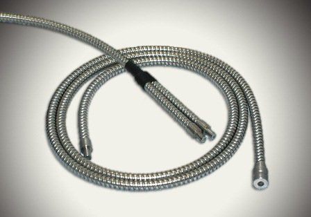
Bundle assemblies are typically designed and manufactured for lighting applications and signal collection. Because the bundle assembly incorporates a multitude of fibers, end terminations can be configured into various shapes. In addition to circular, bundle terminations can be square, rectangle, triangular, circle within a circle, linear, segmented; just about any conceivable geometric shape. This characteristic allows the engineer to “shape” the output profile to suit the application.
The typical bundle design for signal application is the bifurcated type; one common end and two distal ends. Typically a circular configuration, the common end is the transmitter/receiver. One bifurcated leg acts as the transmitter , the other as the receiver.
Other signal configurations include circle within a circle and linear.
When designing for signal transmission, it’s important to understand and control cross talk; the chance for transmitted signal to jump directly to receiver fibers without passing through the filter or reflecting off a target.
Bundle construction emphasizes parallel alignment of all fibers in the termination, which can only be achieved by packing the bundle tightly.
When building plastic fiber bundles, heat management practices are also considered.